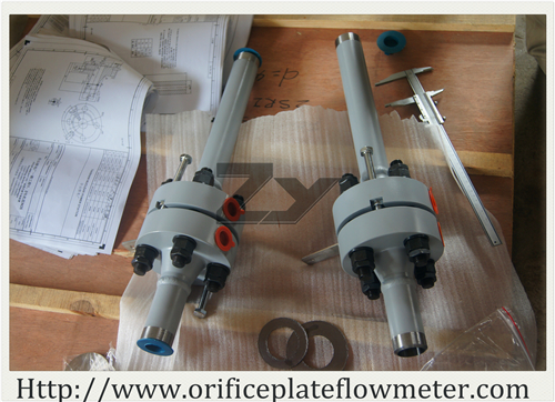
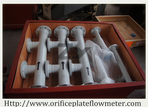
Once the flow calculation is complete, the physical attributes of the flow meter can then be designed. There are several standard making authorities who have developed guidelines for the physical design of primary flow meters such as orifice plates. These include ASME MFC-3M, ISO 5167, AGA 3, PTC-6 (Performance Test Code) and PTC-19.5. Based on the details of these standards, the physical attributes of the meter such as bore design, bore location, pressure tap design, pressure tap location, required pipe straight run requirements, flow conditioning requirements, pipe material, pipe thickness, etc., can be determined.
These physical attributes are accumulated into an engineering design drawing which is utilized for the manufacture of the orifice plate or other flow meter. The product is then manufactured with very tight tolerances. In the case of a PTC-6 Nozzle, deviations in measured bores as small as 3/1000th of an inch can lead to a meter that meets the code requirements and one that does not. As such the manufacturing process is tightly controlled and detailed measurements are taken to ensure that the flow meter will perform as expected.
Steps required to design an orifice plate or orifice plate flow meter:
1. Identify the physical attributes of the piping system.
a. Pipe size
b. Pipe schedule
c. Flange rating
d. Orifice plate material
2. Identify and accumulate data on process flow conditions
a. Fluid to be measured
b. Pressure
c. Temperature
d. Viscosity
e. Flow rates (Minimum, Normal and Maximum)
3. Identify and accumulate information on other requirements of the flow meter
a. Desired differential pressure
b. Target beta ratio
c. Acceptable permanent pressure loss
d. Maximum flow velocity
Note: The flow calculation will provide much of this data, but consideration of this data is crucial to the overall piping system design.
4. Complete the pictorial or graphical depiction of the flow element including
a. Pipe size
b. Pipe schedule
c. Flange size
d. Flange schedule
e. Flange rating
f. Pipe length
g. Pipe bore attributes such as smoothness, roundness, etc.
h. Tap design
i. Tap location
j. Tap orientation
k. Orifice plate details
l. Tagging requirements
m. Other requirements such as welding and non-destructive examination procedures
The process of designing and manufacturing primary flow elements such as orifice plates and other flow meters involves a high level of accuracy not only in the manufacturing process, but also in the data accumulation and calculation process. Many information sources regarding flow calculations provide simplified versions of the detailed flow calculations. These should not be used for detailed design of orifice plates or any other differential pressure flow meter such as flow nozzles or venturi because they do not consider the vast number of correction factors and detailed fluid properties that are needed to ensure the most accurate meter possible. Reputable flow meter engineers and manufacturers can be useful as expert resources to support the flow meter design effort.
These flow calculations can be provided by the engineering staff at ZY Flowmeter. either as a support to the manufacturing of a meter or as a separate contract service. If you need additional information or would like to obtain a flow calculation for your piping design, please refer to the engineering staff on our Contact Us page.


